
PLATE & SHELL HEAT EXCHANGERSHeating · Cooling · Condensation · Heat recovery

Search JINCHEN

Plate & Shell Heat Exchanger Technology

Engineering the interaction between plate geometry, flow distribution, heat transfer, phase behaviour and mechanical integrity.

How a Plate & Shell Heat Exchanger Works

A Plate & Shell Heat Exchanger combines a welded plate pack with a surrounding pressure-containing shell. Thin corrugated plates are arranged so that the spaces between neighbouring plates carry alternating hot and cold streams. Welded boundaries around the ports and outer edges keep these circuits separate. Heat crosses the metal plate between adjacent channels; the two fluids do not need to mix to exchange energy.

The plate-side stream enters through port-connected passages. The shell-side stream enters through a shell connection and is guided into the open-edge passages of the pack. The shell contains the assembly and provides space for the required connections and flow arrangement. In a counter-current arrangement, the two streams travel in opposing overall directions, preserving the temperature driving force along the surface. Actual routing, passes and nozzle allocation depend on the selected configuration.

Corrugations create a large heat-transfer surface within a compact volume and influence mixing, velocity and resistance to flow. These effects cannot be selected independently. A higher local heat-transfer coefficient may be offset by excessive pressure loss or uneven channel loading. Similarly, adding plates changes the number of parallel paths and the velocity within them. Engineering selection therefore brings together the temperature programme, fluid properties, available pressure drop and distribution on both sides. The animation illustrates the relationship between the external connections and internal circuits; the engineering topics below explain why each design decision matters.

INTEGRATED ENGINEERING

One Exchanger. Multiple Engineering Disciplines.

A Plate & Shell Heat Exchanger cannot be designed from heat-transfer area alone. Plate geometry, channel gap, velocity, pressure loss, phase distribution, materials, welding and mechanical loading interact. A change that helps one part of the duty can create a constraint elsewhere.

Mixing ↔ pressure lossHigher turbulence can improve heat transfer but requires more pressure head.

Passage size ↔ thermal intensityWider channels may improve fouling tolerance while changing velocity and heat transfer.

Phase behaviour ↔ usable surfaceVapour and liquid distribution can govern condenser or evaporator performance.

Materials ↔ joint reliabilityCorrosion resistance and welding behaviour must be assessed together.

Thermal, hydraulic and mechanical design form one integrated system.

Explore the engineering

01 / ENGINEERING TOPIC

Plate Geometry & Channel Design

Plate geometry determines how fluid moves across the surface. Corrugation angle and pressing depth influence turbulence, local mixing and the support between neighbouring plates. Together with channel gap, these features affect channel velocity, pressure drop and the space available for suspended solids. There is no single best geometry: the appropriate combination depends on the process duty and its operating range.

More intensive mixing can improve heat transfer, but it also consumes pressure head. Wider channels may suit viscous or fouling fluids and larger particles, while providing less thermal intensity at the same flow rate. Selection therefore considers fluid properties, fouling tendency and solids handling alongside thermal duty. Geometry should be evaluated at reduced flow as well as the design point.

Geometry is a process choice, not a universal optimum.

Explore Plate Geometry & Channel Design →
02 / ENGINEERING TOPIC

Welded Plate-Pack Technology

Individual thin plates form a continuous sequence of alternating flow channels. Each plate separates the fluids on its two faces. Welds around the port openings alternate with welds around the outside perimeter, establishing separate flow boundaries through the plate pack. These process channels do not require interplate gaskets; any shell-cover seal serves a separate mechanical function.

Plate pairing and weld layout determine both fluid routing and structural behaviour. The pack must accommodate differential pressure, thermal expansion and changes in temperature without losing channel integrity. Adding surface area by increasing plate count also changes pack length, restraint and flow loading. The engineering task is to combine a compact surface with pressure integrity and structural stability throughout the specified operating cycle.

One thin plate separates two neighbouring fluid channels.

Explore Welded Plate-Pack Technology →
03 / ENGINEERING TOPIC

Flow Distribution

A correctly sized heat-transfer surface can still underperform when some channels receive too much fluid and others too little. Inlet arrangement, nozzle position and flow directors influence how effectively the available area is used. Unequal channel loading can create stagnant zones, local fouling and pressure losses that are not represented by a simple average velocity.

Distribution becomes especially important when liquid and vapour are present together. Their different densities and changing volume fractions can cause separation before the stream reaches the heat-transfer surface. Plate-pack orientation, liquid supply and vapour routing must therefore be assessed together. The design objective is useful, reasonably uniform channel loading over the intended operating range, rather than merely increasing the installed area.

Available area matters only when the flow uses it effectively.

Explore Flow Distribution →
Heat dutyPressure drop
04 / ENGINEERING TOPIC

Thermal & Hydraulic Design

The heat balance establishes the required duty, while the temperature programme defines the driving force, often expressed through the logarithmic mean temperature difference (LMTD). Film coefficients on both sides, plate resistance and fouling allowance contribute to the overall heat-transfer coefficient. These inputs determine an initial surface requirement, not a finished exchanger selection.

Channel velocity links the thermal calculation to the hydraulic check. Raising velocity may improve the film coefficient, but increases pressure loss through channels, ports and connections. Adding parallel flow paths can reduce pressure drop while changing heat-transfer performance. JINCHEN selection therefore balances area, flow arrangement, allowable pressure drop and thermal margin. The chosen configuration must also be checked against changes in flow, viscosity and temperatures rather than rated only at one favourable point.

Balance the required duty with the available pressure head.

Explore Thermal & Hydraulic Design →
05 / ENGINEERING TOPIC

Condensation & Evaporation

Two-phase duties require more than a liquid-to-liquid sizing method with different properties. During condensation, vapour volume decreases along the flow path. Distribution and condensate drainage influence how much surface remains available, while non-condensable gases can add resistance. Pressure drop changes the local saturation temperature, and any required subcooling adds a distinct part of the duty.

During evaporation, liquid supply and circulation must support stable boiling as vapour quality increases. Poor distribution can leave some channels short of liquid, raising dry-out risk, while other regions remain underused. Phase separation and outlet routing also affect operation. Condensation and evaporation therefore share a need to coordinate thermal performance, hydraulic behaviour and phase management, but their flow arrangements must be selected for the specific service.

Changing phase changes the flow as well as the heat duty.

Explore Condensation & Evaporation →
06 / ENGINEERING TOPIC

Mechanical Design

Thermal performance is useful only if the exchanger remains mechanically reliable. The shell provides pressure containment, while the plate pack and its restraints respond to pressure differences and thermal movement. Operating and design conditions must therefore include both sides of the exchanger, potential differential pressure and the temperatures reached during start-up and shutdown.

Differential thermal expansion, cyclic operation and fatigue can govern details that a steady-state rating does not reveal. Nozzle loads from connected piping, support conditions and installation loads also enter the assessment. Restraint must maintain structural integrity while accommodating the intended movement. Pressure-vessel design principles, material behaviour and the specified operating cycles guide the final mechanical configuration; maximum pressure and temperature values alone do not describe its complete service requirements.

Design for pressure, movement and operating cycles together.

Explore Mechanical Design →
07 / ENGINEERING TOPIC

Welding Engineering

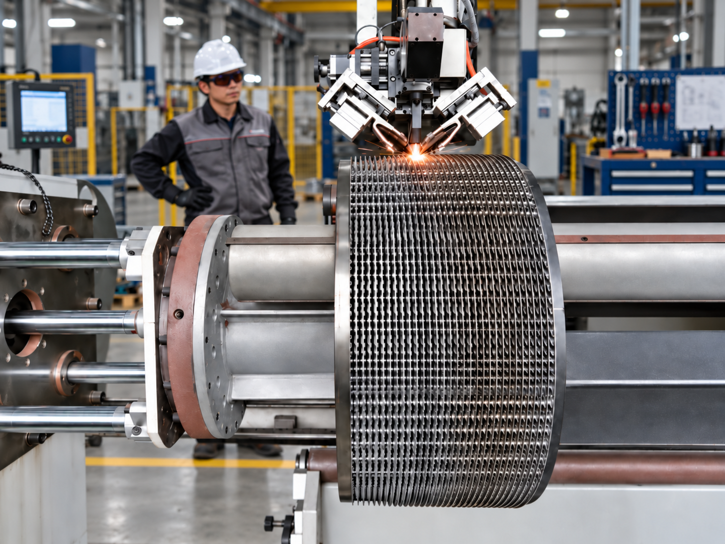
Weld engineering defines how thin sheets become reliable flow boundaries. Seam location and joint geometry must provide continuity around the ports and perimeter without obstructing the intended channels. Penetration must be sufficient for integrity, while heat input and the heat-affected zone must be controlled to suit the material and sheet thickness.

Too much distortion can affect plate fit-up, channel spacing and the repeatability of subsequent joints. Material compatibility, restraint and the joining sequence therefore influence both weld quality and pack geometry. Seam details also need to account for pressure loading and fatigue under temperature or pressure cycling. The technology question is how to achieve a repeatable, inspectable joint with appropriate properties, rather than how many welding machines a factory operates.

A reliable seam preserves both the boundary and the channel.

Explore Welding Engineering →
08 / ENGINEERING TOPIC

Fouling Control

Fouling begins with the process: deposits may arise from particles, precipitation, biological growth or temperature-dependent reactions. Viscosity, solids content and wall temperature help identify the likely mechanism. Velocity and wall shear can discourage some deposits, but increasing velocity also raises pressure loss and may be unsuitable for erosive solids. Channel gap influences both passage size and local flow conditions.

A fouling allowance cannot replace this assessment. Additional area can change velocity, while a wider passage does not guarantee a clean surface. Cleanability must be considered during selection, including access, cleaning-fluid compatibility and the materials exposed during cleaning. The aim is to balance thermal performance, fouling tolerance and a practical maintenance method for the actual fluid, with operating experience used to refine the design assumptions.

Plan for deposits and cleaning while selecting the exchanger.

Explore Fouling Control →
ENGINEERING WORKFLOW

From process conditions to equipment

The selection process starts with the actual process duty, not a fixed model number. Thermal, hydraulic, mechanical and material decisions are progressively combined before the final exchanger configuration is released for manufacturing. These decisions are reviewed together and revisited when a constraint changes.

  1. 01

    Process Data

    Define both fluids and operating cases.

  2. 02

    Thermal Duty

    Establish heat load and temperature targets.

  3. 03

    Channel & Flow Design

    Select geometry, passes and distribution.

  4. 04

    Hydraulic Check

    Check pressure loss on both sides.

  5. 05

    Mechanical Design

    Assess pressure, movement and loads.

  6. 06

    Material Selection

    Confirm compatibility and joining requirements.

  7. 07

    Manufacturing

    Release the agreed exchanger configuration.

  8. 08

    Inspection & Testing

    Verify against the agreed inspection scope.

  9. 09

    Finished Equipment

    Supply the exchanger and project documentation.

Need a Plate & Shell Heat Exchanger Selection?

Send both fluids, flow rates, inlet and required outlet temperatures, operating and design pressures and temperatures, allowable pressure drops, material requirements and fouling information.

Send Your Process Data